
Abstract
Studies on voltage unbalance have revealed its detrimental effects on the operation of three-phase induction motors (TPIM) due to the production of negative-sequence current and torque. Voltage unbalance has been defined in different ways over the years, and each of these definitions is limited in scope in one form or the order, e.g. the neglect or inadequate consideration of the phase angle of the supply in these definitions. The complex voltage unbalance factor captures the phase angle using the ratio of the sequence components, but there is a challenge on the interpretation of the random angle θv with respect to the supply. In this study, a novel definition of phase unbalance is proposed which considers the normal 120° displacement of the three phases of the supply. A comparative analysis of all the definitions is presented using four operational supply case studies for a TPIM, and the results may ultimately impact control strategies.
1 Introduction
Motor design parameters such as stator–rotor slot design (Qiu et al. 2019) and power supply quality affect the operation of electrical motors. A three-phase equipment is designed to operate under balanced three-phase supplies, but due to operational realities a three-phase supply may become unbalanced when there is uncoordinated switching of the line currents, imbalanced transformer windings, faulty transformer windings, unequal single-phase loads on each of the three phases of the supply, etc. (dos Santos Pereira et al. 2018). Voltage unbalance increases operational losses (de Castro e Silva et al. 2016), causes harmonic currents in windings (Gnacinski 2008), and can result in thermal transients in machines (Gnaciński et al. 2018). Power quality is a top notch requirement in electrical systems, and power quality issues are aggravated when supply networks are unstable or unreliable due to frequent switching ON/OFF of power generators or renewable sources, and circuit breakers in a power system. High inductive loads in factories without adequate reactive power compensation can also result in line voltage variations and unbalance.
Voltage unbalance creates negative-sequence current and torque that impairs the operation of a three-phase induction motor (TPIM) (Gnacinski and Tarasiuk 2016; Faiz et al. 2004; Palácios et al. 2014). Voltage unbalance is defined as a condition when the voltage magnitude of the three phases is unequal or when the phase angles deviate from the normal values or when both conditions simultaneously occur (Pillay and Manyage 2001; Adekitan et al. 2019a, b). The phase sequence of a three-phase system is determined by the order in which the phases attain a positive maximum as the phasors rotate in a counter-clockwise direction. A three-phase supply system has the three phases displaced by 120° from each other in a balanced system, as shown in Fig. 1 where Voa, Vob, and Voc are phase-to-neutral voltages, and Vab, Vbc, and Vca are line-to-line voltages such that \( V_{\text{Line}} = \sqrt 3 \times V_{\text{phase}} \). When the phase angle shifts from the balanced 120° phase displacement, a voltage unbalance has occurred, and the triangular three-phase voltage profile will become as shown in Fig. 2. Voltage unbalance has been mathematically defined by National Electrical Manufactures Association (NEMA), IEEE and IEC, but each of these definitions has its deficiencies. Also, none of these definitions considered the implication of phase angle deviations from the 120° normal phase shift. A new definition that directly relates unbalance with the phase angles of the three phases is proposed and analysed in this study. The strength and weaknesses of the proposed phase unbalance index for supply imbalance measurement were analysed using different supply scenarios, and the findings are presented in this study for easy comparison of voltage supply quality in terms of phase angle normality as demonstrated by the proposed definition of phase unbalance.

Phase displacement of a balanced three-phase supply

Balanced versus unbalanced three-phase voltage
2 Voltage Unbalance Definitions
In order to create a comparative index for measuring voltage unbalance towards setting industry regulations and guidelines, various definitions of voltage unbalanced were developed as listed below.
-
1.
NEMA
Voltage unbalance was defined by NEMA, as shown in Eq. (1) (Pillay and Manyage 2001). This definition only considers voltage magnitude.
-
2.
IEC Definition
According to IEC 60034-26, Voltage Unbalance Factor (VUF or Kv) (Quispe et al. 2005; Adekitan and AbdulKareem 2019) is the ratio of the negative-sequence voltage (V2) to the positive-sequence voltage (V1). Also, this definition ignores the phase angle.
-
3.
Complex Voltage Unbalance Factor (CVUF)
CVUF improves on the VUF definition by considering the phase angle θv and the voltage magnitude as defined in Eq. (3). Since \( \theta_{\text{v}} = \theta_{2} - \theta_{1} \) in complex polar notation, various combinations of \( \theta_{1} \) and \( \theta_{2} \) will give the same \( \theta_{\text{v}} \). The pioneer study by Yaw-Juen (2001) refers to the angle θv as somewhat random. CVUF is based on the sequence component, and it is not unique, with an infinite combination of voltages giving the same level of unbalance (Hiendro 2010). This therefore does not clearly reflect the extent of the phase shift among the phases though it may be used with further analysis for estimating peak currents and losses during unbalance (Singh Shashi and Singh Asheesh 2013; Anwari and Hiendro 2010).
Similarly, the sequence current unbalance ratio can be expressed as Kc.
-
4.
Proposed definition of Phase Unbalance (Ph UB)
In order to demonstrate the significance of the impact of angular deviations from the normal 120° phase-to-phase displacement, a new definition for the angular phase unbalance is proposed in Eq. (5) as the ratio of the maximum angular deviation to the 120° reference value.
3 The Methodology
To comparatively examine the proposed definition using a MATLAB-based simulation, a model of a star connected, ungrounded, three-phase induction motor was developed with a positive-sequence impedance (ZM1) of 3.0642 + 3.2266i Ω, and negative-sequence impedance (ZM2) of 0.2336 + 0.4194i Ω obtained using Eqs. (6) and (7), operating at a rated slip of 0.025 and rated power of 25 kW. The motor was analysed using a 415-V three-phase supply with balanced phase angles \( V_{\text{ab}} \angle 0^\circ \), \( V_{\text{bc}} \angle 240^\circ \;{\text{or}}\;V_{\text{bc}} \angle - 120^\circ \), and \( V_{\text{ca}} \angle 120^\circ \). The values of 240 V/415 V were taken as the rated average phase and line supply voltages. Four cases (A to D), each having five supply scenarios, were considered, as shown in Tables 1 and 2. Scenario 1 for the four cases depicts a balance supply with equal voltage magnitudes across the three phases and angular displacement of 120° among the phases. Table 1 shows the phase-to-neutral voltage for each of the three phases for the four cases considered, while Table 2 shows the equivalent line-to-line voltage as the three-phase voltage triangle becomes unbalanced. Each case of the supply scenario was applied to the three-phase induction motor, and the results are presented comparatively with respect to the proposed definition of phase unbalance.
In Eqs. (6) and (7), subscript 1 stands for positive-sequence parameters and 2 for negative-sequence parameters, Xs and Rs are the stator reactance and resistance, Xr and Rr are the referred rotor reactance and resistance, respectively, Xm is the magnetizing inductance, s is the rotor slip.
4 Results and Analysis
For the four cases considered, in case A, the phase-to-neutral voltage magnitude was kept constant, while the phase angle for each of the phase voltage was varied from the balanced 120° inter-phase displacement. In case B, the phase-to-neutral voltage magnitude was also kept constant, but the manner of phase angle variation of phase Vbn and Vcn was interchanged. In case C, the phase angles are balanced and equally displaced by 120°, while the phase voltage magnitudes deviated from the rated value, thereby creating a distortion in the line-to-line voltage magnitude and phase displacement. In case D, both the phase voltage magnitudes and the phase angle displacements were allowed to deviate from the balanced state in order to compare the extent of the effect of simultaneous deviations in both parameters from the balanced state.
The goal of these analyses is to identify patterns with the different manner of possible voltage unbalance scenarios. The results are presented in Table 3 for case A, Table 4 for case B, Table 5 for case C, and Table 6 for case D. The tables show the positive- and negative-sequence line voltage components Vseq1 and Vseq2, the positive and negative-sequence current components Iseq1 (A) and Iseq2 (A), NEMA and CVUF (VUF and θv) calculation of voltage unbalance, sequence current ratio (kc < θc), and the proposed phase unbalance definition (Ph UB).
The following highlights the key findings in this study
-
1.
Using phase A as reference, case A and case B are quite similar with the angular deviations occurring in Phase B of case A, occurring in Phase C of case B, and angular deviations in Phase C of case A occurring in Phase B of case B. The phase voltage magnitude remained constant and equal at 240 V, but the angular deviations created an unbalance in the resulting line-to-line voltages, as shown in Table 2. From Tables 3 and 4, the result shows that the sequence voltage and current are equal in magnitude for both cases, although the phase angles are different. Ultimately, this created equal Kv and kc for both cases, and this implies that when similar phase angle variations occur on alternate windings, the effective voltage unbalance remains unchanged.
-
2.
Cases A and B also confirm the significance of supply phase angle deviations from the balanced value. With the phase voltage magnitudes remaining constant, NEMA unbalance definition using phase voltage resulted in zero unbalance (0%), whereas NEMA definition using the line-to-line voltage magnitude reveals the prevailing unbalance, thereby confirming that phase angle unbalance alone triggers generation of negative-sequence voltage component. This further reveals that when the \( \sqrt 3 \) relationship between phase and line voltage no longer holds due to phase angle deviations from the 120° inter-phase displacement, NEMA voltage unbalance definitions using phase and line voltage magnitudes will not be equal. The use of the line and phase voltage as alternatives in NEMA magnitude-based voltage unbalance definition assumes that the \( \sqrt 3 \) relationship is constant, but this is not so when the inter-phase angular deviation varies from 120° (unbalance) in the three-phase voltage triangular profile.
-
3.
In case C, the phase angles were maintained at rated value, while the magnitude of the phase voltage was varied, and this translated to deviations in the line–to-line voltage of the three-phase supply. In case D, both the phase angle and the magnitude of the phase voltage were varied simultaneously, and the results are distinct from that of case C. In case C, while the NEMA unbalance using line voltage is 3.12%, for case D it is 9.5% even though the magnitude of the phase voltage for the two cases is the same. This implies that when a simultaneous deviation in voltage magnitude and phase angle occurs from the balanced state, a more significant voltage unbalance is created (Adekitan et al. 2019a, b). The NEMA definition based on phase voltage remained the same for case C and case D, and this is because the phase angle deviations in case D are only reflected in the magnitude of the resulting line voltage.
-
4.
Figures 3, 4, 5, and 6 show comparatively the difference in the supply imbalance as defined using VUF, NEMA_L, and the new Ph UB approach. The variations of the magnitude of angle (θv) for CVUF for the cases considered do not reveal any meaningful pattern that can help with the interpretation and quality comparison of the different supply scenarios, and this emphasizes the random nature of θv.
Fig. 3 
Case A: comparative plot of VUF (%), Ph UB (%), and NEMA (%)
Fig. 4 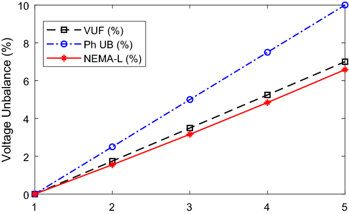
Case B: comparative plot of VUF (%), Ph UB (%), and NEMA (%)
Fig. 5 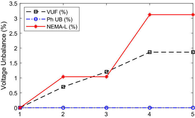
Case C: comparative plot of VUF (%), Ph UB (%), and NEMA (%)
Fig. 6 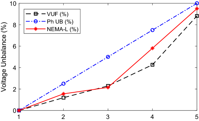
Case D: comparative plot of VUF (%), Ph UB (%), and NEMA (%)
-
5.
The new Ph UB definition is based on the phase angle deviation as expressed in the definition of voltage unbalance, and as such, the extent of the unbalance is measured by how much the phase angle deviates from the normal value which makes the interpretation easy.
-
6.
The new Ph UB definition may also be limited because it is based on the phase angle and does not incorporate variations in line voltage magnitude, as revealed in Fig. 5, for case C where the phase angles are kept at rated value, but the voltage magnitudes are unbalanced. Therefore, there is a need to combine Ph UB definition with magnitude-based definitions for a robust definition of voltage unbalance.
-
7.
The current unbalance ratio kc, as shown in Fig. 7, reveals significant variations for the four cases considered. The greatest increase in the value of kc occurred in case D when both magnitude and phase angle deviations occurred in the power supply. Values of kc that are up to eleven times that of Kv have been reported in various studies (Enrique Quispe and Lopez 2015). This emphasizes the impact of supply imbalance on the variations of the sequence current of a three-phase induction motor.
Fig. 7 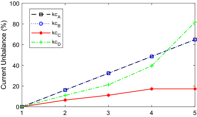
Comparative plot of the sequence current unbalance (kc)
-
8.
To prevent motor damage when operating under unbalanced voltage supply, the motor should be derated as recommended by NEMA. For the new Ph UB definition, the derating factor (PhUB_DF) is defined by Eq. (7) which was modified to track the derating factor recommended by NEMA MG-1 Standard on motors and generators (Reineri et al. 2006), as shown in Fig. 8. Using curve fitting techniques, an approximate polynomial function was developed for both the NEMA and Ph UB definition of the derating factor, as shown in Eqs. (8) and (9). The approximated third-order polynomial functions are plotted in Fig. 9.
Fig. 8 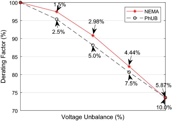
Derating factor
Fig. 9 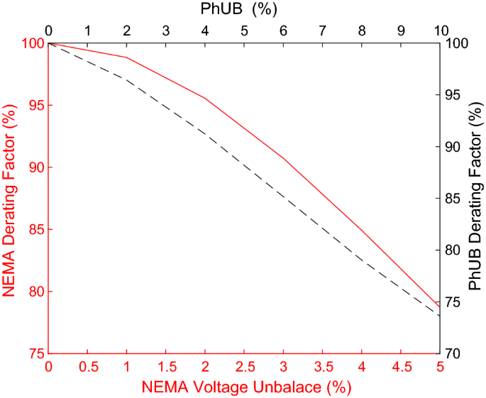
Approximated derating factor using polynomial function


Phase angle deviations stimulate a greater increase in the generation of sequence currents, and losses as compared to voltage magnitude unbalance (Garcia et al. 2009; Adekitan et al. 2019a, b), and this further emphasizes the need to clearly consider and define phase angle unbalance. All the available definitions so far are not perfect yet, the θv associated with CVUF is quite random, NEMA definition using phase and line voltage are not exactly the same when phase angle is considered, and the proposed Ph UB is based on phase angle deviations, and may be inadequate when only phase voltage magnitude variation occurs.
5 Conclusion
The phase unbalance Ph UB (%) definition proposed in this study directly relates supply unbalance with the angular phase of each of the three phases of a three-phase supply, as expressed in the theoretical definition of voltage unbalance. Ph UB (%) reveals that even when the phase voltage magnitudes of the three-phase supply are equal, negative-sequence current can still be generated by phase angle deviations from the normal 120° inter-phase displacement. The study identifies weakness and strength of the NEMA, VUF, CVUF, and Ph UB (%) definitions of voltage unbalance. A derating factor plot was developed using the new Ph UB definition to show the relationship with the NEMA-based derating factor curve. The combination of Ph UB (%) and magnitude-based definitions may be used as an improved definition of voltage unbalance, which considers both the magnitude and phase angle shifts in the three-phase supply. Opportunity still exists for further investigations towards evolving a more robust definition and understanding of the significance and the impact of phase angle deviations on supply imbalance analysis.
Change history
11 April 2021
A Correction to this paper has been published: https://doi.org/10.1007/s40313-021-00722-z
References
Adekitan, I. A., & AbdulKareem, A. (2019). The significance of the mode of voltage imbalance on the operation and energy losses of 3-phase induction motor. Engineering and Applied Science Research, 46(3), 200–209.
Adekitan, A., Ogunjuyigbe, A. S., & Ayodele, T. R. (2019a). The impact of supply phase shift on the three phase induction motor operation. Engineering Review, 39(3), 270–282.
Adekitan, A. I., Samuel, I., & Amuta, E. (2019b). Dataset on the performance of a three phase induction motor under balanced and unbalanced supply voltage conditions. Data in Brief, 24, 103947. https://doi.org/10.1016/j.dib.2019.103947.
Anwari, M., & Hiendro, A. (2010). New unbalance factor for estimating performance of a three-phase induction motor with under- and overvoltage unbalance. IEEE Transactions on Energy Conversion, 25(3), 619–625.
de Castro e Silva, M. D., Ferreira Filho, A. L., Neves, A. B. F., & Mendonça, M. V. B. (2016). Effects of sequence voltage components on torque and efficiency of a three-phase induction motor. Electric Power Systems Research, 140(Supplement C), 942–949. https://doi.org/10.1016/j.epsr.2016.03.051.
dos Santos Pereira, G. M., Fernandes, T. S. P., & Aoki, A. R. (2018). Allocation of capacitors and voltage regulators in three-phase distribution networks. Journal of Control, Automation and Electrical Systems, 29(2), 238–249. https://doi.org/10.1007/s40313-018-0367-x.
Faiz, J., Ebrahimpour, H., & Pillay, P. (2004). Influence of unbalanced voltage on the steady-state performance of a three-phase squirrel-cage induction motor. IEEE Transactions on Energy Conversion, 19(4), 657–662.
Garcia, D. C., Anésio Filho, L., Oliveira, M. A., Fernandes, O. A., & do Nascimento, F. A. (2009). Voltage unbalance numerical evaluation and minimization. Electric Power Systems Research, 79(10), 1441–1445.
Gnacinski, P. (2008). Effect of unbalanced voltage on windings temperature, operational life and load carrying capacity of induction machine. Energy Conversion and Management, 49(4), 761–770. https://doi.org/10.1016/j.enconman.2007.07.033.
Gnaciński, P., Pepliński, M., & Hallmann, D. (2018) Thermal transients of induction machine under changeable voltage unbalance. In 2018 XIII international conference on electrical machines (ICEM), 2018 (pp. 1338–1343). IEEE.
Gnacinski, P., & Tarasiuk, T. (2016). Energy-efficient operation of induction motors and power quality standards. Electric Power Systems Research, 135(Supplement C), 10–17. https://doi.org/10.1016/j.epsr.2016.03.022.
Hiendro, A. (2010). A quantities method of induction motor under unbalanced voltage conditions. Telkomnika, 8(2), 73–80.
Palácios, R. H. C., da Silva, I. N., Goedtel, A., Godoy, W. F., & Oleskovicz, M. (2014). A robust neural method to estimate torque in three-phase induction motor. Journal of Control, Automation and Electrical Systems, 25(4), 493–502. https://doi.org/10.1007/s40313-014-0118-6.
Pillay, P., & Manyage, M. (2001). Definitions of voltage unbalance. IEEE Power Engineering Review, 21(5), 50–51.
Qiu, H., Zhang, Y., Yang, C., & Yi, R. (2019). The influence of stator-rotor slot combination on performance of high-voltage asynchronous motor. Journal of Control, Automation and Electrical Systems. https://doi.org/10.1007/s40313-019-00502-w.
Quispe, E., & Lopez, I. (2015). Effects of unbalanced voltages on the energy performance of three-phase induction motors. In 2015 IEEE Workshop on Power Electronics and Power Quality Applications (PEPQA), 2015 (pp. 1–6). IEEE. https://doi.org/10.1109/PEPQA.2015.7168237.
Quispe, E., Vigeo, P., & Cogollos, J. (2005). Statistical equations to evaluate the effects of voltage unbalance on the efficiency and power factor of a three-phase induction motors. WSEAS Transactions On Circuits And Systems, Brasil, 4(4), 234–239.
Reineri, C. A., Gómez, J. C., Balaguer, E. B., & Morcos, M. M. (2006). Experimental study of induction motor performance with unbalanced supply. Electric Power Components and Systems, 34(7), 817–829. https://doi.org/10.1080/15325000500488636.
Singh Shashi, B., & Singh Asheesh, K. (2013). Precise assessment of performance of induction motor under supply imbalance through impedance unbalance factor. Journal of Electrical Engineering, 64, 31.
Yaw-Juen, W. (2001). Analysis of effects of three-phase voltage unbalance on induction motors with emphasis on the angle of the complex voltage unbalance factor. IEEE Transactions on Energy Conversion, 16(3), 270–275. https://doi.org/10.1109/60.937207.
Funding
Open Access funding enabled and organized by Projekt DEAL.
Author information
Authors and Affiliations
Corresponding author
Additional information
Publisher's Note
Springer Nature remains neutral with regard to jurisdictional claims in published maps and institutional affiliations.
The original online version of this article was revised due to a retrospective Open Access order.
Rights and permissions
Open Access This article is licensed under a Creative Commons Attribution 4.0 International License, which permits use, sharing, adaptation, distribution and reproduction in any medium or format, as long as you give appropriate credit to the original author(s) and the source, provide a link to the Creative Commons licence, and indicate if changes were made. The images or other third party material in this article are included in the article's Creative Commons licence, unless indicated otherwise in a credit line to the material. If material is not included in the article's Creative Commons licence and your intended use is not permitted by statutory regulation or exceeds the permitted use, you will need to obtain permission directly from the copyright holder. To view a copy of this licence, visit http://creativecommons.org/licenses/by/4.0/.
About this article

Cite this article
Adekitan, A.I. A New Definition of Voltage Unbalance Using Supply Phase Shift. J Control Autom Electr Syst 31, 718–725 (2020). https://doi.org/10.1007/s40313-020-00579-8
Received:
Revised:
Accepted:
Published:
Issue Date:
DOI: https://doi.org/10.1007/s40313-020-00579-8